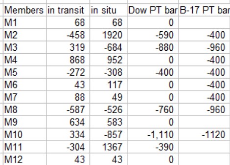
The table of "P.T. BAR REQUIREMENTS" which I have quoted from the engineers' drawing sheet B-17 from the MCM-FIGG proposal for FIU pedestrian bridge pdf,
is
not accurate and the requirements must have been recalculated and updated before construction because member #11
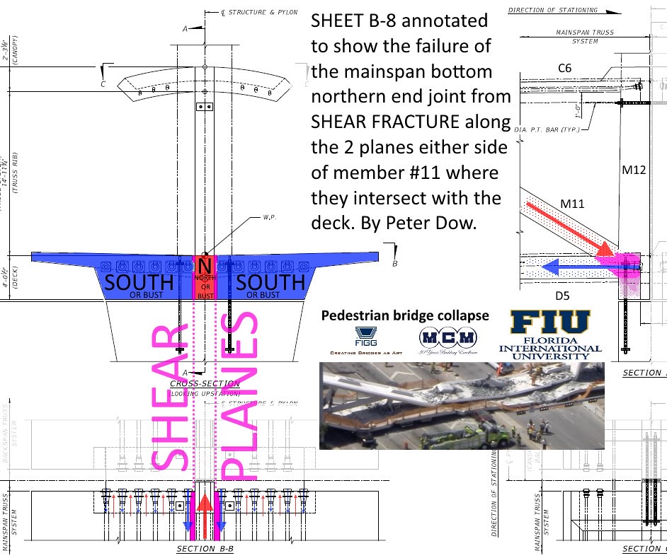
did have 2 P.T. bars fitted - as the photographic and video evidence of them taken in the ruins of the collapsed bridge proves.
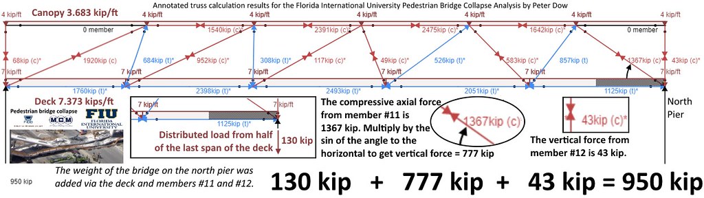
I have recently posted here results of my own calculations of the truss member forces (compression or tension, in transit and in situ).
Now I have calculated what the appropriate P.T. bar tensioning requirements really were and produced this table and bar chart.
I calculate the P.T. requirement as a factor of about 1.3 times the greatest tension force that the member experiences, being half-way between the minimum tension acceptable and that times the load safety factor of 1.6 for a live load. 1.3 x is half way between the two acceptable extremes.
As you can see there is little agreement between my calculated P.T. bar tensioning requirements and what was initially proposed in B-17.
Here is my blow by blow analysis of each of the P.T. bar requirements of truss members 1 to 12.
M1 - Our figures agree that no P.T. bar force is required. Having said that, any concrete column that is being moved around or subject to vibration, side loads or possible earthquake forces would resist tensile fracture far better by prestressing so "no P.T. bar required" should not be taken to mean "no prestressing is required". For this kind of job, I would assume that some kind of prestressing is a "must" throughout.
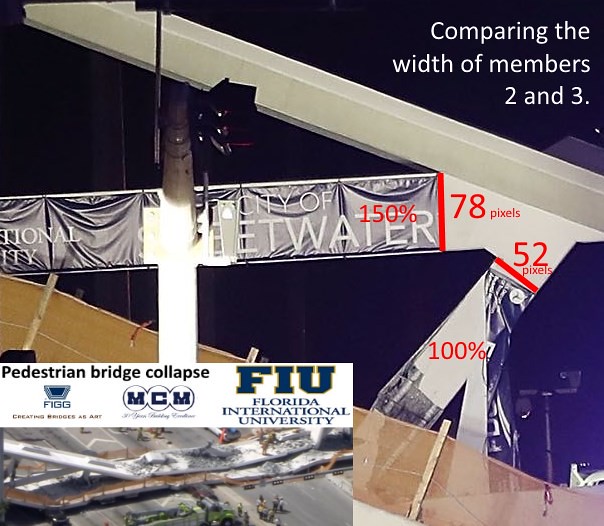
M2 - B-17's "400" is even lower than the calculated tension in transit and this would cause a failure of M2 in tension. M2 also experiences more compressive force than any other member and so one might be curious as to why M2 was not the weakest link in the bridge that failed first?
As this photograph of the south end of the collapsed bridge shows, M2 was constructed 150% of the width of M3 and of all the other members.
We may presume that it was as a consequence of the special reinforcement which M2 received which allowed it to survive at least until M11 had failed.
M3 - B-17's "960" is higher than I calculate it needs to be.
M4 - Is always under compression so M4 doesn't need the P.T. bars that B-17 recommends.
M5 - Our figures agree that "400" is the correct P.T. bar force. However, because M5 is always under tension, I don't agree that a concrete column is required at all. The design would save weight by replacing the M5 reinforced concrete column with a M5 suspension cable.
M6 & M7 - Like M4 are always under compression, though the compressive force is so small (117 kip at most) I might speculate that calculations might reveal that the truss could hold up well enough without
any M6 or M7 members at all and weight saved by a redesign involving
- removing M6 & M7 from the design altogether,
- moving the bottom node of M5 to the node where M8 meets D4,
- D2&D3 merging to become one member and
- C3&C4 merging to become one member too.
M8 - As per M3, B-17's "960" is higher than it needs to be and as per M5 this is a member that is always under tension and should be replaced by a much lighter suspension cable.
M9 - As per M1.
M10 - Remarkably close agreement.
M11 - The "bad boy" member #11 that B-17 forgot. We don't know what P.T. bar tension had been set or was being set when the bridge collapsed happened. I would recommend 390 kip, all other things being equal.
M12 - As per M1.