That NTSB video helped a lot.
Like I said, the smoking gun.
You mean each stressed within the specified range?
Sheet B-17, page 115, recommends a P.T FORCE/BAR between 200 KIPS and 320 KIPS depending on the truss member concerned.
Remember that if one of the P.T.bars failed - snapped in tension - as the evidence indicates - that could be because the operator of the jack exceeded the recommended force for a 1 3/4" diameter bar, beyond the rated, say, 150 KSI and it snapped at somewhere about 2.4 square inches x 150 KSI = 360 KIPS.
So at failure you might have had a modest 260 KIPS on one P.T. bar that survived fine and 360 KIPS on the one that was being over-jacked and failed, snapped in tension.
So we might estimate a total force of 620 KIPS from both bars.
With regard to the dead load and my previous calculation for the compressive stress on member #11.
Actually, the figure quoted everywhere on the internet now for the weight of the mainspan is
950 tons which is an increase of 35 tons from the "915 tons" stated in the proposal pdf.
So because
and now assuming the 950-tons figure for the dead load, the updated calculation is
950 tons = 950 x 2000 = 1,900,000 lbs = 1,900 KIPS
Half the weight of the mainspan =
0.5 x 1,900 KIPS = 950 KIPS
The compressive bridge dead load in member #11, the force transmitted from the other truss members, was
1.7 x 950 = 0.85 x 2 x 950 = 0.85 x 1,900 = 1615 KIPS
So
1615 KIPS rather than the "1555 KIPS" I had previously calculated for the effect from the dead load.
Now add in the compressive load to resist the tension in the bars - 620 KIPS
The total compressive load on member #11 - bridge + bars = 1615 + 620 = 2235 KIPS
I think you may be drawing the wrong conclusions.
You see if the bar snapped - failed in tension - it was because the concrete had survived the compressive load up until the point of snapping - the damage to the concrete seen was due not to an initial failure of the concrete in compression but from the initial explosive release of elastic energy from the snapping bar.
If the concrete had initially failed in compression then the bar would likely not have snapped.
There was a fight between the bar and the concrete - and initially the good strong concrete won - initially the bar snapped and in snapping it exploded part of the concrete as a secondary effect - the part of the concrete that was next to the failing bar.
I might suggest that to be "safe", the construction industry might be better discontinuing the use of thick P.T. bars such as 1 3/4" - since we can see what happens when they fail - disaster.
With 0.6" diameter tendons if one of those snaps it is not so much energy released explosively - only about 12% of energy released explosively compared to the energy released from a 1 3/4" diameter bar.
So constructing with 0.6" diameter tendons is much safer than constructing with thick P.T. bars - the thinner bars are more idiot proof.
Well I had some help.
")

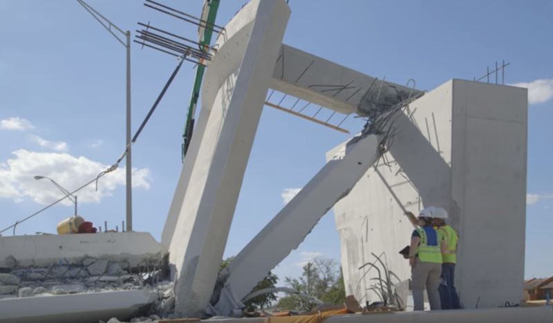 Damage
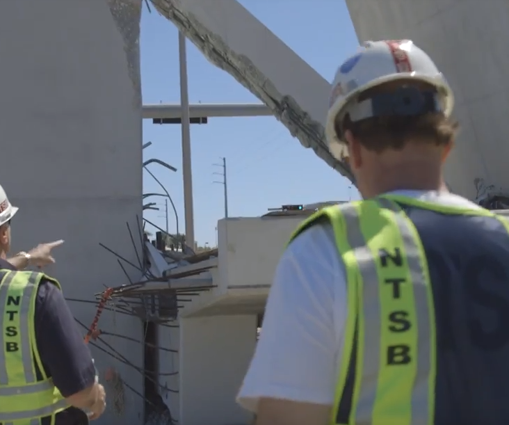


 than than the 1615 KIPS that I calculated for the bridge load on member #11, WITHOUT the additional compression from the P.T. bars.