exchemist
Valued Senior Member
I had this pop up on my screen when I was browsing the forum about 6 hours ago
https://getvoltex.com/article4?gclid=EAIaIQobChMI5YnMs5PH7wIVBUvVCh1vEwBxEAEYASAAEgKTi_D_BwE
Except that it was tailored to the UK, with money in pounds (but the numbers were the same! )
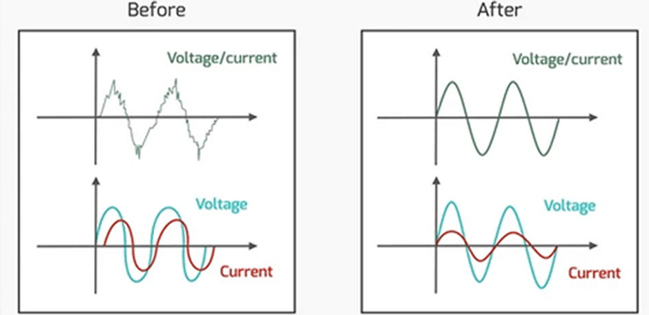
This seems to be a "power factor" scam, by which people are conned into thinking that any offset between volts and amps creates a power loss. However, since any component of current that is orthogonal to the voltage is a "wattless current", this does not represent a power loss (well to be strict, it does, very, very slightly, due to resistance in the mains wiring through which the wattless current flows, but that is all).
I was shocked to see this on the forum. It seems to be a well-known scam.
I rather enjoyed to compulsory crank reference to Tesla, though.
https://getvoltex.com/article4?gclid=EAIaIQobChMI5YnMs5PH7wIVBUvVCh1vEwBxEAEYASAAEgKTi_D_BwE
Except that it was tailored to the UK, with money in pounds (but the numbers were the same! )
This seems to be a "power factor" scam, by which people are conned into thinking that any offset between volts and amps creates a power loss. However, since any component of current that is orthogonal to the voltage is a "wattless current", this does not represent a power loss (well to be strict, it does, very, very slightly, due to resistance in the mains wiring through which the wattless current flows, but that is all).
I was shocked to see this on the forum. It seems to be a well-known scam.
I rather enjoyed to compulsory crank reference to Tesla, though.